
Tesla Model X side pole test, front view. GIF created from this video from CrashNet1 on YouTube.
Tesla Model X side pole test, overhead view. GIF created from this video from CrashNet1 on YouTube.
Tesla Model X: center underbody
I joined Tesla in January of 2013 as an engineer on the Body Structures team. This team is responsible for the design and development of a car’s body structure, sometimes referred to as the body-in-white. This structure serves as the “skeleton” of the vehicle, a strong frame to carry all of the vehicle’s systems and provide a number of performance characteristics. The design of the body structure is driven by crash performance, global stiffness, cost, and manufacturing requirements, among many other factors. I worked first on Model S cost- and mass-down studies, before leading the design of the right-hand drive variant for the body team; I took lead on the design of the center underbody system for Model X; and I was lead again on the center underbody system for Model 3. On this page, I seek to highlight my work on the Model X.
On the Tesla Model X, I took charge of my first complete subassembly - the center underbody of the body structure. This area is composed of the side sill members, seat crossmembers, toeboard area, floor panel, and various mounting and fixing brackets. As with all of my projects at Tesla, my responsibilities covered the entire range of the design process. Involved from initial concept generation all the way to production ramp, I owned the physical design (3d CAD) of each of my components. For each part (and the larger subassembly) I was responsible for system performance, material selection, manufacturing feasibility, cost, mass, GD&T, and joining strategy, among other things.
The Model X structure is an evolution of the Model S design: almost entirely aluminum, it uses large cast nodes and extruded profiles with stamped panels. The focus for Model X was to adapt and improve the Model S body structure to handle larger vehicle loads, reduce body cost, and simplify body assembly.
Tesla Model S early underbody and rolling chassis. The Model X underbody uses a similar architecture. Section A-A is marked for detail in the next images. Illustration over original image credit hybridcars.com.
Tesla Model X body structure rear view. Section B-B is marked for detail in the next images. Illustration over original image credit Tesla.
The driving crash load case for the components I designed was the rigid pole side impact test, part of FMVSS 214. In this test, the vehicle strikes a rigid pole sideways. The 10-inch (254mm) pole is positioned in line with the head of the driver, and the vehicle moves at 20mph (32 kph) at a 15-degree angle into the pole. Injury values are calculated and combined with door opening requirements to calculate a performance score.
This test is particularly challenging for electric vehicles with large batteries, because these battery packs are typically mounted beneath the occupant cabin, and close to the side of the car where the pole strikes. The interaction between the pole and battery pack is extremely important, and varies with different battery architectures; at Tesla, it was crucial that the battery cells receive no damage during the crash event. Our design approach was to establish two distinct zones, much like any other crash case: first, the deformable zone, composed of parts designed to crush and absorb the kinetic energy of the pole; and a rigid backup structure zone, composed of extremely strong parts that would not yield, but instead function as a backstop to enable the deformable zone to do its job.
Simplified illustration of Model S side pole impact structure. Original image property of Pall Kornmayer.
Simplified illustration of Model X side pole impact structure. Note the single-piece sill extrusion and the taller seat crossmember for the raised occupant position. Original image property of Pall Kornmayer.
The illustrations above show the components of the system. The primary element of the deformable zone is the one-piece aluminum extruded side sill. In Model S, this was a two-piece assembly composed of a thinner “outer” extrusion made of a fairly standard alloy, with a thicker “insert” extrusion made of a high-strength alloy. Breaking the sill into two components carried many benefits for a young Tesla - please note that the following is my conjecture, as I did not design the system. By divorcing the sill into two components, they could tailor each to its specific function: the outer could provide the geometry required for the overall vehicle package, using lower wall thickness and a general-purpose aluminum alloy. The insert could be thicker and made from a stronger alloy, tuned for the crash loads. Stronger material is typically more expensive as a raw material and also more difficult to “push” on the extrusion die, leading to higher costs. I believe that this construction also gave Tesla a design advantage: at this early phase in Tesla’s engineering development, CAE material correlations may not have been as developed as they are today. A standalone insert design gave the engineering team the ability to make late changes to the geometry or material used in the insert if initial testing uncovered issues or opportunities for improvement.
Model S side sill in quasi-static test rig. Note the inner and outer extrusion elements. Original photo property of Pall Kornmayer.
Model X side sill. Note the single-piece construction. Original photo property of Pall Kornmayer.
However, two-piece construction had disadvantages as well. The first is dimensional variation: extrusions are typically quite stable along their length, but when the parts in question are roughly 2 meters long even a small deviation adds up. With two long extrusions you compound the potential for fitment issues. The first Model S design had to carry generous gaps to account for this dimensional variation, reducing local package efficiency. There is also the mass, cost, and manufacturing impact of needing to join these two components with glue and mechanical fasteners. Finally, use of a special or proprietary alloy can sometimes tie you to a single-source vendor. The procurement team is not a fan of this.
For Model X, we took advantage of increased design time to pursue an integrated, one-piece sill design. Working through multiple iterations of dual- and single-piece designs, we were able to develop a single-piece profile made from a very common grade of aluminum. We were able to better utilize the entire sill in the deformation mode, while reducing part count and associated complexity. A number of different geometries were crushed in quasi-static testing to validate the concept before first vehicle-level tests. We worked with our part supplier to define both a minimum material requirement for our sills, and a testing scheme (including a unique physical test rig on-site at the extrusion plant) to validate incoming part quality.
Model S side sill after quasi-static test. Original photo property of Pall Kornmayer.
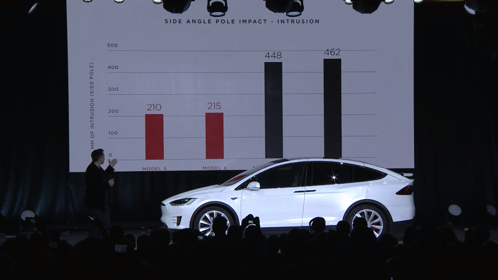
Elon highlights the low pole intrusion value during the Model X launch event. Image created from this video from Teslafiniti on YouTube.
The result of our work is a 5-star overall NHSTA rating with an extremely low probability of occupant injury. Our side pole strategy was validated through testing and the Model X delivers not only a 5-star rating in this test, but also the third-lowest intrusion ever measured in a production vehicle, behind only the Model S and the Model 3. [Note: at time of writing I’m not sure where Model Y stacks up]
Another unique challenge that the Model X center underbody had to take on was the mounting of the second row “monopost” seats. Rather than a more conventional square-shaped mounting frame, these seats use a single large post to mount to the floor of the vehicle. The seat belts are mounted to the seats themselves, not the upper body, further compounding the load applied to the floor structure in crash cases. And just to make sure it wasn’t too easy, it was all mounted on long tracks for generous fore-aft movement for occupant access to the third row.
Tesla Model X second-row “monopost” seats. Image credit Chicago Motor Cars.
Model X “monopost” seat patent image. The seat is supported by a single, heavy-duty central structure that travels in tracks fastened to the floor structure. Image credit Tesla patent via Google Patent Search.
In a way, these seats were enabled by the fact that Model X is an electric vehicle with a large battery pack mounted under its floor. I designed a short and wide crossmember, stretching its footprint as much as possible to help react the moment imparted by the long seat tracks, and secured the crossmember to the battery pack with a series of bolts. In this way the loads from the seat were reacting not just against my short crossmember, but against the tall battery box as well. Engaging the battery pack to bolster the body structure was a constant goal at Tesla, and some recent EVs have followed in that path.
